I like taking things apart, figuring out how they work, and see if they can perhaps gain a bit of Open Source, either by replacing existing software (as is commonly done with OpenWrt for replacing router vendor firmware, ESPHome for replacing firmware on ESP devices, etc.) or by adding some hardware that can run the code I want.
However, taking things apart, maybe even soldering some pins, or desoldering a flash chip to read it, is scary. Over the last few years I’ve been working myself up from hacking on 5 EUR devices (Wemos D1 Mini) to 20-30 EUR devices (I recently dared to solder pin headers to the Silvercrest/Lidl Zigbee gateway - I know, it’s only pin headers, but I’m taking it slow. I also put together an airRohr recently, which involved soldering tons of wires to three devices).
Getting good at something means doing it a lot. Doing something that may destroy devices a lot costs money. So, I went to the local thrift store, looking for hardware to poke at. I found two old Sitecom APs/repeaters - a WL-330 and a WL-114, for € 2.50 each. A steal! This post is about the WL-330, or “Wireless Range Extender N300”. It’s not a very useful device in 2022, but it has all the parts that routers have today - a semi-decent SoC, some RAM, some flash, one Ethernet port, and of course, WiFi.
The text below was written weeks after I actually did all of this poking. There may be accidental omissions, and mistakes.
Other documentation
While I was working on this device, somebody pointed me to Hardware Hacking Experiments by Jérémy Brun-Nouvion (PDF). It is a very good collection of methodology for inspecting unknown devices, and it contains clear instructions for some of the things you’ll see me do below. You should definitely read it before, after, or next to this article.
Opening, serial
Step one - open it up. Just a few screws at the bottom and the top came off nicely:
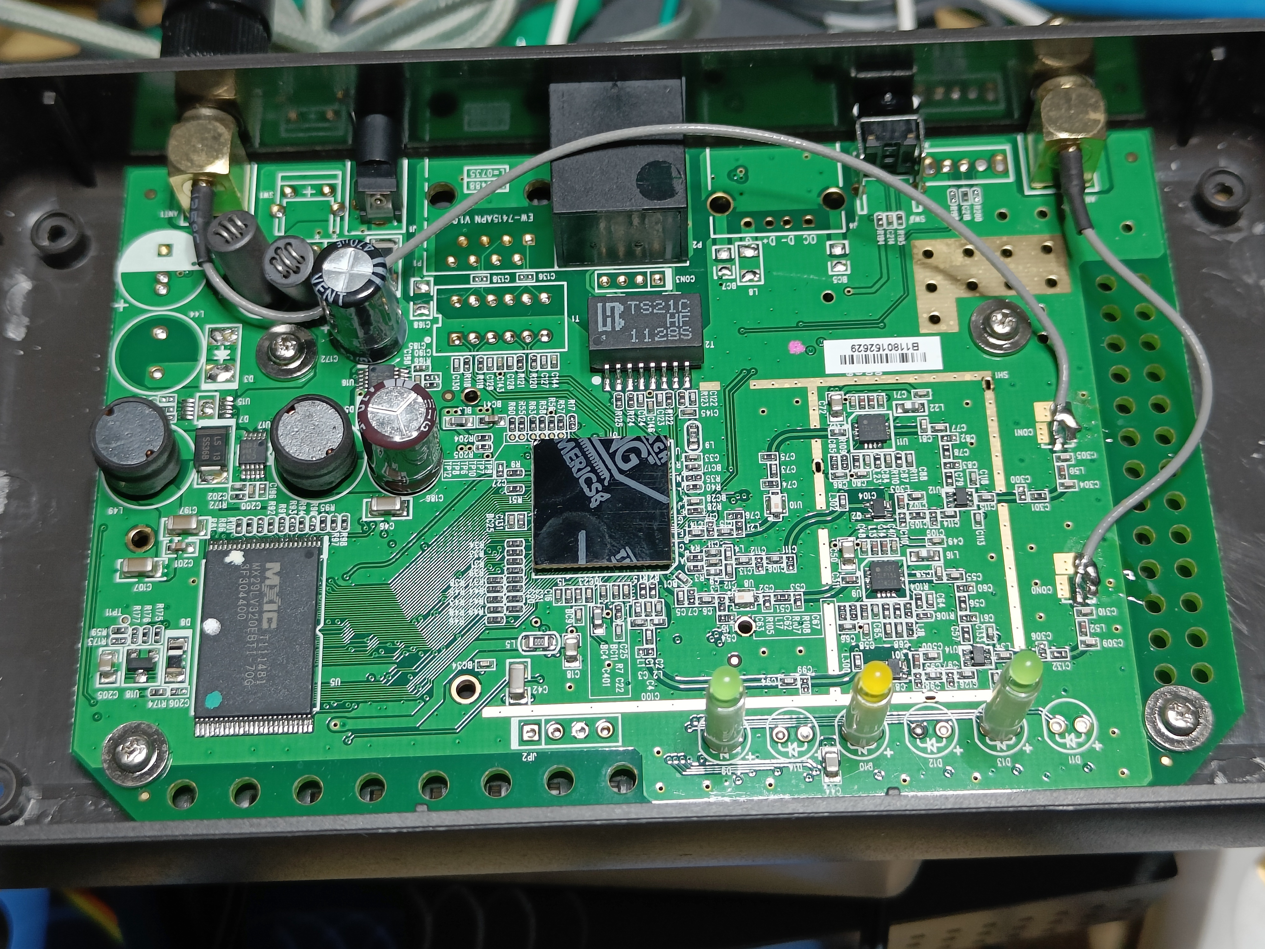
There’s lots to see here! Two antenna connectors at the top, with the Ethernet port in the middle. To the right of that, an unpopulated spot that really looks it could be USB? Bottom left (“MXIC”) is a flash chip. The CPU, in the middle, has no useful markings. I’ve documented what I know on wikidevi.
Bottom middle, marked JP2, we find 4 unpopulated holes, one of which is square. I’ve learned over time that such a set is quite likely to offer serial console. Armed with my multimeter, I tried to figure out what hole is what. GND is easy - it usually offers little to zero Ω of resistance to actual ground (the outside of the barrel jack power connector). With GND sorted, I found two pins at 3V3 compared to GND. One of those is actual 3V3 - we’re going to ignore that. The other one likely is TX (in TTL serial, an idle TX is at Vcc, which is 3V3 for this board).
I did not solder - JP2 is nicely located near the edge of the board, which means this debugging clip (2.54mm, single row is the one I used here) would easily fit right on the edge of the board:
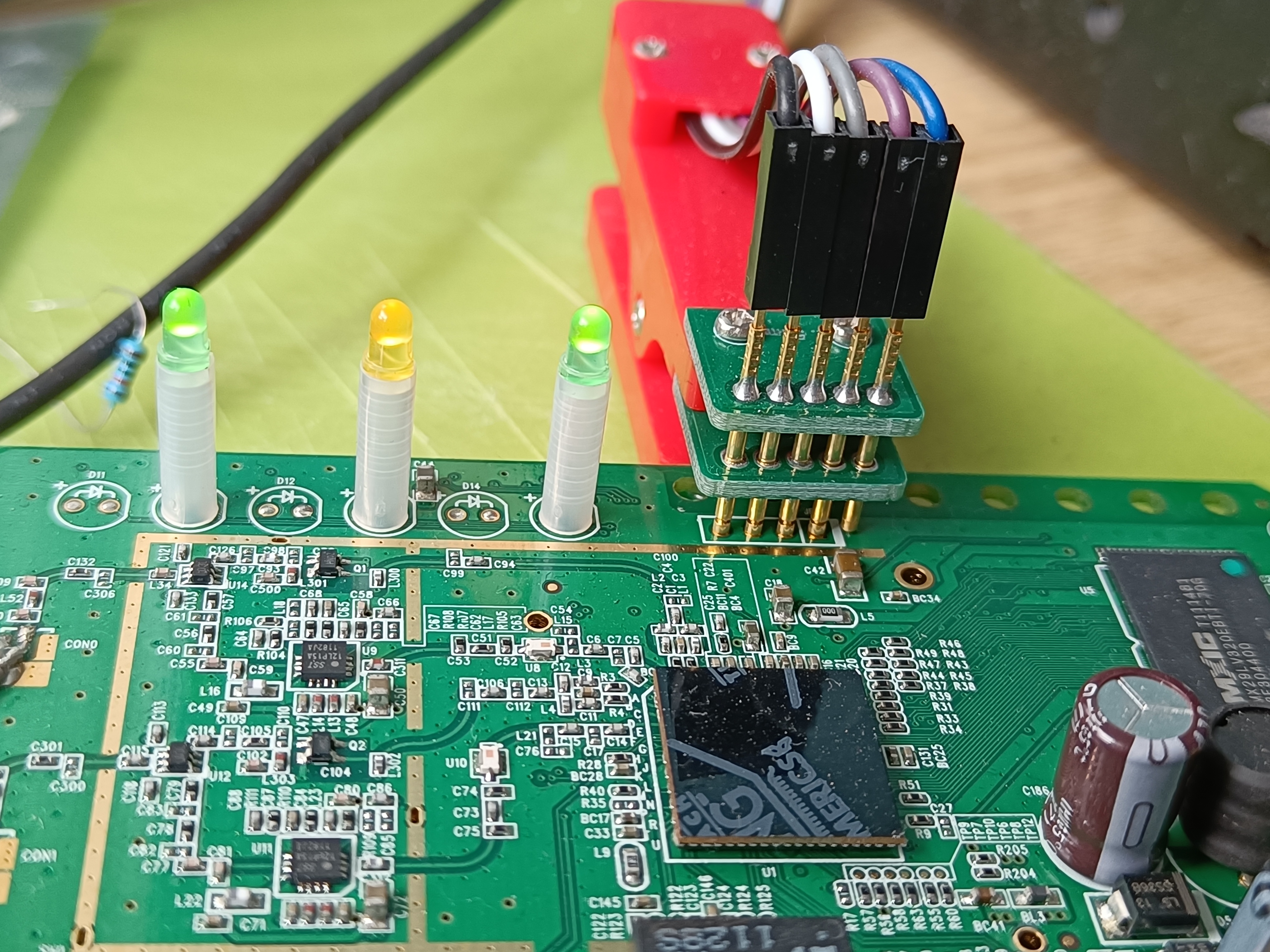
The left 3 wires go to a USB-serial TTL adapter. If you don’t have one, the right pins on a Raspberry Pi also work.
With serial connected, I powered the device up.
Boot
U-Boot greeted me:
U-Boot 1.1.3 (Nov  7 2008 - 13:35:55)

Board: Ralink APSoC DRAM:  16 MB
relocate_code Pointer at: 80fa8000
****************************
Init GPIO Pin****************************
flash_protect ON: from 0xBFC00000 to 0xBFC26213
protect on 0
protect on 1
protect on 2
protect on 3
protect on 4
protect on 5
protect on 6
protect on 7
protect on 8
protect on 9
flash_protect ON: from 0xBFC30000 to 0xBFC3FFFF
protect on 10
*** Warning - bad CRC, using default environment

============================================
Ralink UBoot Version: 3.1
--------------------------------------------
ASIC 3052_MP1 (MAC to GigaMAC Mode)
DRAM COMPONENT: 256Mbits
DRAM BUS: 16BIT
Total memory: 32 MBytes
Flash: 4 MBytes
Date:Nov  7 2008  Time:13:35:55
============================================
icache: sets:256, ways:4, linesz:32 ,total:32768
dcache: sets:128, ways:4, linesz:32 ,total:16384

 ##### The CPU freq = 384 MHZ ####

SDRAM bus set to 16 bit
 SDRAM size =16 Mbytes

Please choose the operation:
   0: Load ucos code to SDRAM via TFTP Client.
   1: Load system code to SDRAM via TFTP.
   2: Load system code then write to Flash via TFTP.
   3: Boot system code via Flash (default).
   4: Entr boot command line interface.
   9: Load Boot Loader code then write to Flash via TFTP.
and proceeded with option 3 after a second:
You choosed 3

^H^H^H 0

3: System Boot system code via Flash.
## Booting image at bfc50000 ...
Bad Magic Number,43535953
   Image Name:   Linux Kernel Image
   Created:      2009-01-15   3:11:08 UTC

 System Control Status = 0x20440000
   Image Type:   MIPS Linux Kernel Image (lzma compressed)
   Data Size:    3059628 Bytes =  2.9 MB
   Load Address: 80000000
   Entry Point:  8028f000
   Verifying Checksum ... OK
   Uncompressing Kernel Image ... OK
No initrd
## Transferring control to Linux (at address 8028f000) ...
## Giving linux memsize in MB, 16

Starting kernel ...
There’s a very interesting discrepancy here. U-Boot reports 32 MByte of RAM - as does the labeling of the actual RAM chip. However, Linux is told 16. I have not yet figured out why this happens.
After some kernel messages and errors from terribly hacky startup scripts, a very interesting screen greets me:
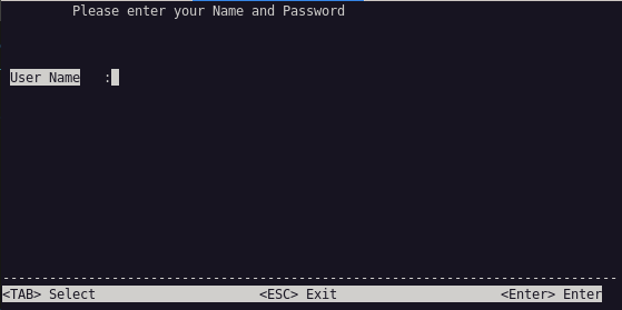
I tried a few things, like admin/admin, but it would not let me in. After some more tinkering and trying things, I found that the reset button would kill this login screen, briefly exposing a root shell! .. until the device rebooted a few seconds later. I considered automating this, to run one or two commands in that brief window, but I parked this idea for later, in case I would not find another avenue.
Boot OpenWrt?
The U-Boot menu offered booting from TFTP. This is an excellent way to test firmware images on a device without destroying anything on the flash. I tried booting a few seemingly suitable (old, because this device does not have a lot of memory) OpenWrt images, but they did not get very far.
Firmware dump
I decided it was time to investigate the firmware. Some people use IC clips to read flash chips directly, but this is not always easy. I dug around in U-Boot a bit, but found no useful commands to dump the flash chip. Then somebody pointed out to me that SPI NOR flash is usually mapped into memory by the CPU/SoC. After some poking, I figured out the address too. So:
RT3052 # md.b bf000000 5000000
bf000000: ff 00 00 10 00 00 00 00 fd 00 00 10 00 00 00 00    ................
bf000010: f9 01 00 10 00 00 00 00 f7 01 00 10 00 00 00 00    ................
bf000020: f5 01 00 10 00 00 00 00 f3 01 00 10 00 00 00 00    ................
bf000030: f1 01 00 10 00 00 00 00 ef 01 00 10 00 00 00 00    ................
bf000040: ed 01 00 10 00 00 00 00 eb 01 00 10 00 00 00 00    ................
...
(5000000 is too much - it’s 4 MByte of flash, not 5, so I got the first megabyte repeated at the end.)
I had screen log all of this to a file. od can then turn this into a big binary blob (sadly I no longer have the exact command I used, but it did involve telling od about the bf000000 offset!).
From the kernel startup log, we get the partition table:
Creating 7 MTD partitions on "Ralink SoC physically mapped flash":
0x00000000-0x00030000 : "Bootloader"
mtd: Giving out device 0 to Bootloader
0x00030000-0x00040000 : "Config "
mtd: Giving out device 1 to Config
0x00040000-0x00050000 : "Factory"
mtd: Giving out device 2 to Factory
0x00050000-0x00160000 : "Kernel"
mtd: Giving out device 3 to Kernel
0x00160000-0x003e0000 : "RootFS"
mtd: Giving out device 4 to RootFS
0x003e0000-0x00400000 : "Cimage"
mtd: Giving out device 5 to Cimage
0x00050000-0x003e0000 : "Uimage"
mtd: Giving out device 6 to Uimage
With a bit of dd, we can carve our 4 MByte flash image into several smaller files.
I tried unpacking the RootFS partition with binwalk -e, but I ran into trouble. My unsquashfs did not support this squashfs image. After trying several patches to squashfs-tools floating around the Internet, I ran into sasquatch which is a nice patchset to squashfs-tools, that actually managed to extract this root file system.
After reading some startup scripts, grepping for some strings, etc., I found /bin/setup to be the program responsible for the weird login prompt.
Binary analysis
With one or two exceptions, the last time I tried to analyse a closed-source binary was back when I was still running MS-DOS - so this seemed like a great opportunity to work on those skills! I installed and started Ghidra, and loaded /bin/setup into it. Because setup is statically linked, I got roughly zero symbols. I poked around a bit, managed to label a few functions (memset and similar simple functions that are easy to recognise in assembly), and got quite a decent overview of program flow, but not enough to figure out what login the tool wanted.
I might go back to that later, I did enjoy it.
Looking for other holes
Based on earlier experience I expected there would be vulnerabilities in the existing software on the router. And I had a dump of all that software!
Here’s something that looked like it had a lot of potential:
$ strings /bin/webs | grep %s | grep /bin
/bin/nbtscan -a -r %s.1-50/24 > /var/netName.var
/bin/nbtscan -a -r %s.51-100/24 >> /var/netName.var
/bin/nbtscan -a -r %s.101-150/24 >> /var/netName.var
/bin/nbtscan -a -r %s.151-200/24 >> /var/netName.var
/bin/nbtscan -a -r %s.201-254/24 >> /var/netName.var
/bin/rftest_old.sh %s %s %s %s %s %s %s %s %s %s %s %s %s %s %s %s %s %s %s %s %s %s %s %s %s %s %s %s %s %s
/bin/storage.sh %s
/bin/rftest.sh %s > /tmp/rftest.out
That looks like argument interpolation, straight into the shell!
Some of the words I found near rftest_old.sh appeared in an ASP file, in /web/wlanMP.asp. So, here’s the exploit:
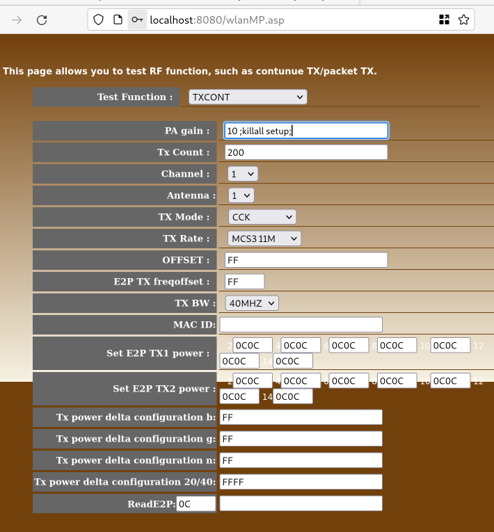
Post the form, and the magic login screen on the serial console disappears, leaving us at a root shell.
Conclusion
Getting root on a device normally is a great first step towards installing open source software on it. However, OpenWrt really does not want to support devices this small so the exercise ends here.
This experience will hopefully one day enable me to actually port OpenWrt to some fun device.
Additional notes
After posting this initially, logic analyzers came up in a related conversation. I realised I completely forgot that chapter in this article.
I’ll keep it short: if you’re trying to read serial with a logic analyzer, make sure your sampling rate is high enough. If, by analyzing time between edges, you conclude that the baud rate must be 125000, realise that this is a nice and clean divisor of your sampling rate (1 Million/second I think) and not actually what is happening.